Dienstag, 15. Dezember 2020

Franzis Adventkalender VW Käfer: kein Ton? No sound on Franzis Advent calender VW beetle?

 My lovely wife gave me the Franzis Advent calendar for this year's pre-Christmas time.

Today, the button for the sound module was the "gift of the day" and it was supposed to start the sound module. Unfortunately, it didn't do anything! So a little analysis showed that the battery box prevents one of the battery contacts to actually get contact! 

But don't worry, here is the solution to the problem: Remove the battery box from the base plate and flip it over, like so:


Then, carefully pry off the cover of the battery contacts:

Then remove material with a file in these areas:


Depending on the type of battery you use, the dimensions might be a little different, but the general idea is, to remove material to allow contact of the "+" side of the battery box.

Assembly in reverse order of assembly and your sound module should sound like a beetle!

On December 24th I will post the complete project!


Mittwoch, 29. April 2020

Oil cooler project finally finished!

After lots of angle grinding, hole drilling and thread cutting, it is finished!
Some details of the 3mm steel plates I used for the brackets (again, captive nuts were used)

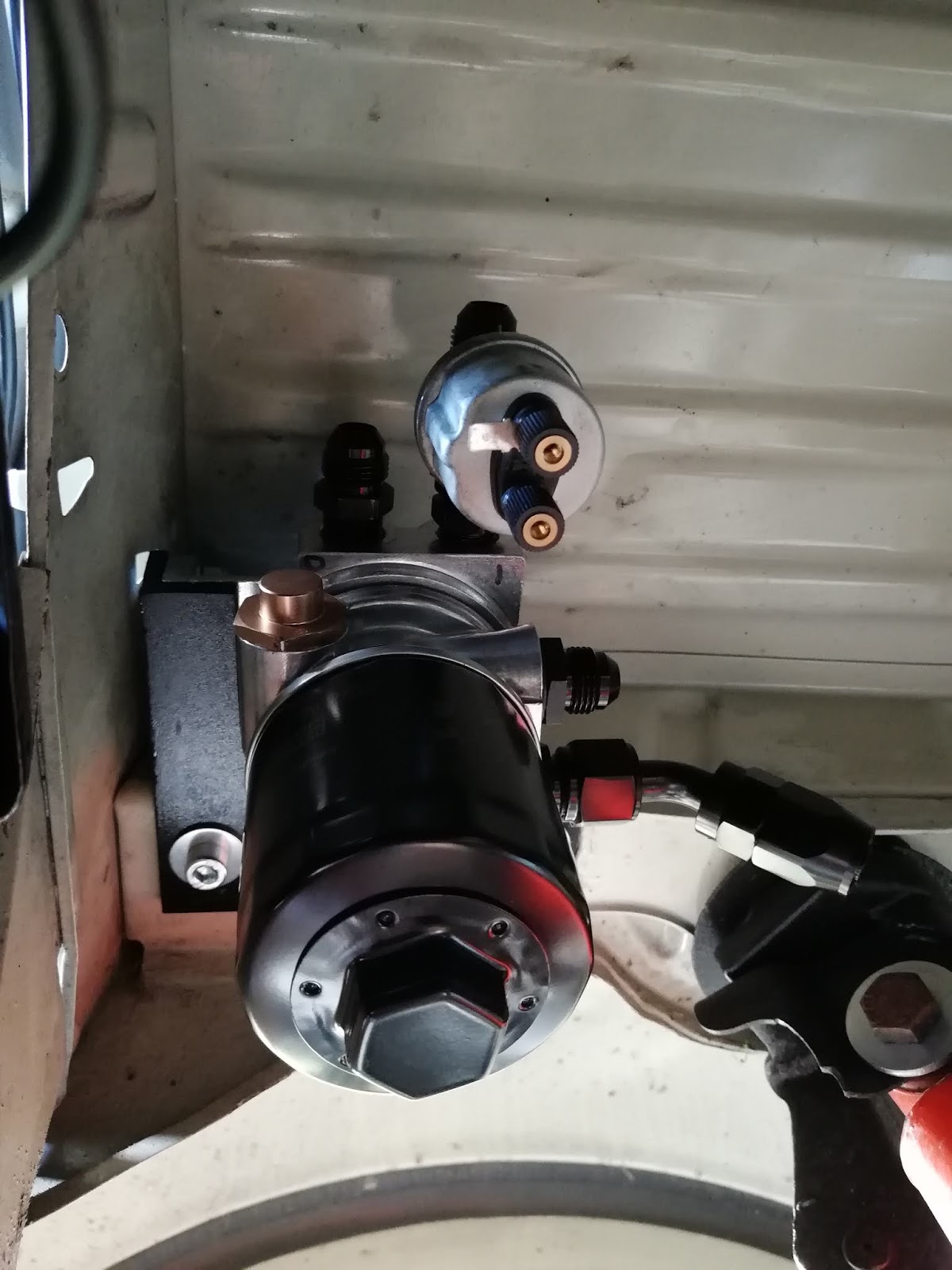
Here is the cooler already fitted, the oil lines are not finished yet in this pic (another set of 6 captive nuts in hindsight of a cover with vents, to be mounted later)

And a view from the side:

And the finished article, plumbed and oil tight!

Currently I am designing a metal shield with cooling fins to improve the already good airflow even more!

Besides the improved cooling abilities, I also wanted to get rid of the "chaos" in the engine bay, I think it worked out well:

before:


after:

(Yes, I know, the vent hoses looks like garden hose, but it was supplied by CB performance, with the Type 3 specific vent housing. It will be replaced with "proper" hose soon!)

all of this cluttered mess is gone:


Here are a few shots of the creating, fabricating and assembly process:


This is the initial sketch - for me, most of it still makes sense, even though, I changed a lot of details along the way...

I also added another piece of sheet metal to improve air flow on the 3/4 cooling tin. There is a rectangular opening to release the hot air, after it passed the oil cooler, here is a pic of such an original cooling tin:

This opening could be closed, now that there is no oil cooler any more, it will improve the cooling of cylinder 3/4 as more air volume will flow over the cylinders now.

Here is the metal cover, I used a simple tab on one side and an existing thread on the other side, thus I could slip the cover onto the already mounted tin:


This is a mock up of the final assembly set up:
 (Of course, the cooling tins on my engine are not that messed up and rusty!)

Dienstag, 21. April 2020

The first cut is the deepest

The oil needs to travel from the adapter to the oil filter, behind the firewall. A hole in the fire wall is a first step. (A lick of rust protective primer hopefully prevents rust on the cut line). To make this mess a whole neater, another aluminium cover, painted in black wrinkle finish, equipped with proper rubber grommets to protect the oil lines was fabricated. M6 Captive nuts allow for a neat installation of the cover:


Major Tom to ground control

"Ground" is the key word here. After final assembly of the oil filter / adapter, the oil temperature / warning light sensor had no ground. So, the oil pressure showed a constant 10 bar and the "idiot light" did not come on. An update in the ground connection was necessary - but how? The sender unit only has 2 contact prongs, one for pressure and one for warning light. The M10x1 thread for attachment to the oil line is conical, so, no way to attach a ground strap...
The solution was to ground the housing itself!
Today shown a little different - In a short photo story:


 (forgive my booger welds)

 a little zinc spray to avoid corrosion

 Ground strap attached! The sender is fully functional again

Freitag, 17. April 2020

Peter Kramer's California Käfer Shop / Stage Fright

Recently I mentioned Peter Kramers "California Käfer Shop" in one of my posts. When he was still located in Dortmund, basically on a scrap yard, this guy had it all, one piece windows, Baja bug kits, cheap taiwanese chrome parts, performance exhausts - you name it. A good amount of my monthly wage in the late 80ies was regularly brought to his shop. I still see the guy from time to time on the Maikäfertreffen or selling Hot Wheels and neon signs in the Techno Classica Fair in Essen, but this shop was the only source for rad Cal look parts since the mid 80ies. Also he sold the American "Hot VW's and Dune Buggies" and "VW Trends" magazines for 5 DM instead of the 12 DM you could buy it for at the book store of the main train station in Essen.Well, he was - and probably is still - a special character, but also thanks to his engagement and his shop, I became the VW nut I am today - and since the mid 80ies!

Here is a key ring I still own, with  the image of his "promotion vehicle" at the time, which he later sold to Helge Ohmes, the famous VW Dragster Bug  "Stage Fright" - originally built in Bakersfield CA by Michael Irvin


The Spaghetti Incident

Yes, another album title, but here it is all about the relocation of the ignition coil and cables, to remove as many cables from visibility:
This lot of wires could be removed

The coil is relocated to the left side of the engine compartment. Almost all wires are invisible now. It will only become apparent after final assembly, but if you compare this to the "before" status, you get the idea: Especially around the oil cooler and coil area, all sorts of wires strewn around


electric fuel pump installation finalized

This is the final set up of the fuel pump:

The bulkhead cover, fuel pump, filter and fuel line as well as the electrical connections, all in their final position, ready to run!

Here is a view from below, the routing of the complete systemcan be seen here:

2 rubber damped clamps lead the fuel line into the perfect contour

Montag, 13. April 2020

old school cool!

With the mechanical fuel pump deleted, I had to cap off the mounting hole for it in the engine block.
I knew I had such a block off plate since years somewhere in my parts stash. I must have bought in the early 90ies in a shop, known to every VW nut in Germany at that time, Peter Kramer's California Käfer Shop located in Dortmund, later moved to Schwerte.

Here it is, a CB performance cover in the old style packaging:


It is a perfect match to the new breather housing:

breathe easy and keep your cool!

A friend of mine offers an upgrade kit for the IDF 40 Weber carbs, allowing to increase the Venturi size from original 28 mm to 34 mm. Also, the spray bar is a completely different design with a more even spray pattern. I purchased this kit already 3 years ago, but never had the itch to mount it. But with the car now in pieces anyways, it was a good time to install the kit:

left side: og spraybar and 28mm venturi (2-pc design) right side: one piece 34 mm venturi with incoporated spray bar

and this is one of the finished carbies, with both new venturies assembled:


When everything will be assembled, I'll also add another heat barrier under the Webers, original VW "Pertinax" seals, of course with enlarged inner diameter to fit to the ported heads:


Packaging the oil filter and thermostat housing

This was an epic challenge. As you probably know, the old air cooled Volkswagens were not equipped with an oil filter, which might be o.k. for a stock engine, but with the added displacement and performance, I wanted to add an oil filter with the external oil cooler. The filter shall be mounted in a way allowing to service it, but not block the access of heater cables, fuel lines, clutch cable etc.

After hours of playing with mounting locations and options how to possibly mount it, I came up with a solution which shall allow to mount it, but also be able to replace it easily. In the left rear area behind the wheel well:

This time I will start with a picture of the final article, but the way to get here wasn't that easy!


With the decision of the location finalized, I had to find a way to mount it here. A bracket of 5 mm thick mild steel was the solution.

It is basically "L"-shaped, following the contour of the filter housing with a 2nd plate welded on, to accept the fixation points of the housing.


and this is the designated position of the bracket (positioned with my fingers only):


With 3 M8 screws attaching the filter to the bracket, it seemed only logical to use more than 3 bolts to mount the whole assembly to the body. So I used 4 M8 captive nuts to for a strong attachment set up:

 
 (Yes, there is a fifth hole, but it wasn't usable, as it is located exactly in a depression of the beam. I used it to fill the beam with fluid film cavity protection and capped it off with a rubber plug)

Here is the sub-assembly of the bracket and filter housing, already attached with lock nuts:


and another picture of the final assembly, mounted into the vehicle:

The oil pressure and warning light sender is also installed here, making the engine compartment a little neater with less cables. Oil hose routing is the next challenge!

electric fuel pump

In an effort to get the engine compartment a little cleaner with as much clutter removed as possible, I will change from a mechanical to an electric fuel pump. It will be attached to the front bulk head. There is a cover already, which I will replace with a self made aluminium one, with incorporated captive nuts for fuel pump attachment.

top is the original bulk head cover, bottom is the aluminium replacement. The og cover has a raised section, which takes away some precious space, so the new one is flat:

I am a big fan of wrinkle finish paint, so I painted this cover with it:

This is the assembled status, with two rubber lined mounting brackets for a robust attachement, but also some noise reduction:

( I marked the direction of flow and also the positive and negative terminal to make sure everything will be assembled flawlessly)

New plate already mounted in the Fastback's bulk head:

The fuel pump has differently sized electrical attachment points, to avoid malfuncton or having the pump running in the wrong direction, so I had to enlarge one of the crimps accordingly:

 A picture of the final assembly will follow soon!