Freitag, 17. April 2020

electric fuel pump installation finalized

This is the final set up of the fuel pump:

The bulkhead cover, fuel pump, filter and fuel line as well as the electrical connections, all in their final position, ready to run!

Here is a view from below, the routing of the complete systemcan be seen here:

2 rubber damped clamps lead the fuel line into the perfect contour

Montag, 13. April 2020

old school cool!

With the mechanical fuel pump deleted, I had to cap off the mounting hole for it in the engine block.
I knew I had such a block off plate since years somewhere in my parts stash. I must have bought in the early 90ies in a shop, known to every VW nut in Germany at that time, Peter Kramer's California Käfer Shop located in Dortmund, later moved to Schwerte.

Here it is, a CB performance cover in the old style packaging:


It is a perfect match to the new breather housing:

breathe easy and keep your cool!

A friend of mine offers an upgrade kit for the IDF 40 Weber carbs, allowing to increase the Venturi size from original 28 mm to 34 mm. Also, the spray bar is a completely different design with a more even spray pattern. I purchased this kit already 3 years ago, but never had the itch to mount it. But with the car now in pieces anyways, it was a good time to install the kit:

left side: og spraybar and 28mm venturi (2-pc design) right side: one piece 34 mm venturi with incoporated spray bar

and this is one of the finished carbies, with both new venturies assembled:


When everything will be assembled, I'll also add another heat barrier under the Webers, original VW "Pertinax" seals, of course with enlarged inner diameter to fit to the ported heads:


Packaging the oil filter and thermostat housing

This was an epic challenge. As you probably know, the old air cooled Volkswagens were not equipped with an oil filter, which might be o.k. for a stock engine, but with the added displacement and performance, I wanted to add an oil filter with the external oil cooler. The filter shall be mounted in a way allowing to service it, but not block the access of heater cables, fuel lines, clutch cable etc.

After hours of playing with mounting locations and options how to possibly mount it, I came up with a solution which shall allow to mount it, but also be able to replace it easily. In the left rear area behind the wheel well:

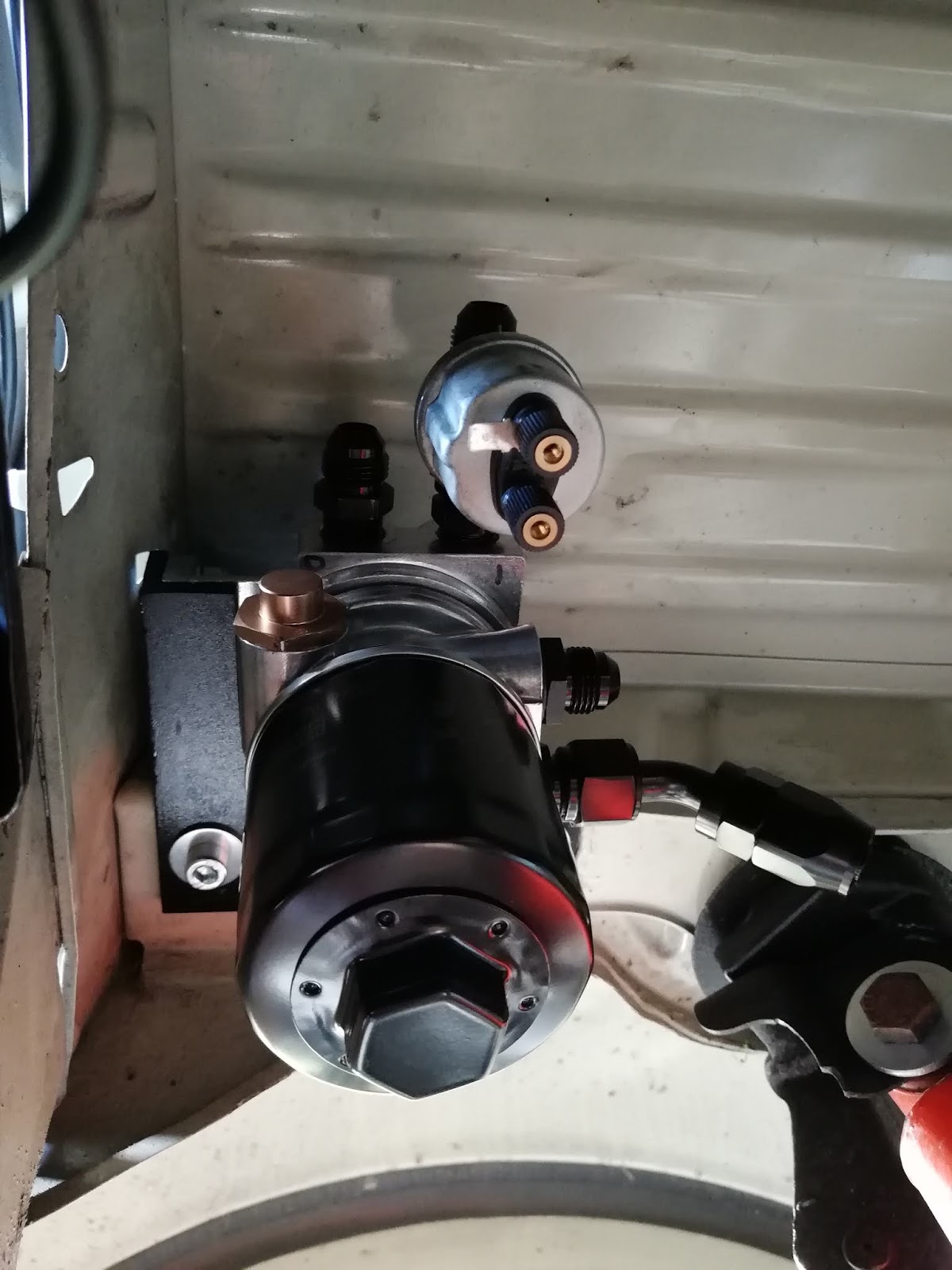
This time I will start with a picture of the final article, but the way to get here wasn't that easy!


With the decision of the location finalized, I had to find a way to mount it here. A bracket of 5 mm thick mild steel was the solution.

It is basically "L"-shaped, following the contour of the filter housing with a 2nd plate welded on, to accept the fixation points of the housing.


and this is the designated position of the bracket (positioned with my fingers only):


With 3 M8 screws attaching the filter to the bracket, it seemed only logical to use more than 3 bolts to mount the whole assembly to the body. So I used 4 M8 captive nuts to for a strong attachment set up:

 
 (Yes, there is a fifth hole, but it wasn't usable, as it is located exactly in a depression of the beam. I used it to fill the beam with fluid film cavity protection and capped it off with a rubber plug)

Here is the sub-assembly of the bracket and filter housing, already attached with lock nuts:


and another picture of the final assembly, mounted into the vehicle:

The oil pressure and warning light sender is also installed here, making the engine compartment a little neater with less cables. Oil hose routing is the next challenge!

electric fuel pump

In an effort to get the engine compartment a little cleaner with as much clutter removed as possible, I will change from a mechanical to an electric fuel pump. It will be attached to the front bulk head. There is a cover already, which I will replace with a self made aluminium one, with incorporated captive nuts for fuel pump attachment.

top is the original bulk head cover, bottom is the aluminium replacement. The og cover has a raised section, which takes away some precious space, so the new one is flat:

I am a big fan of wrinkle finish paint, so I painted this cover with it:

This is the assembled status, with two rubber lined mounting brackets for a robust attachement, but also some noise reduction:

( I marked the direction of flow and also the positive and negative terminal to make sure everything will be assembled flawlessly)

New plate already mounted in the Fastback's bulk head:

The fuel pump has differently sized electrical attachment points, to avoid malfuncton or having the pump running in the wrong direction, so I had to enlarge one of the crimps accordingly:

 A picture of the final assembly will follow soon!

Sonntag, 29. März 2020

re-routing the air flow

When the original type 3 oil cooler is removed, the engine tin needs to be modified. There is a gaping hole left when the external adapter is installed instead of the cooler. The viably important flow of air for the engine would be lost, resulting in even hotter engine temps and possible fatal engine failure.

To avoid that, the cooling tin needs a block-off plate in the former oil cooler area. So, in order to "fabricoble" such a plate, the exact set-up needs to be assembled to measure all dimensions needed.

The first obstacle was the M8/M6 threaded bolt for the oil cooler fixation. I vividly remember the problems I had on the 1776 Streaker engine I assembled some years ago:
Here is the hole story:
https://volksstreaker.blogspot.com/2014/04/cylinders-heads-and-oil-pump-and-some.html


This time I was more clever, soaked the thread bolt over night in penetration oil and used grip pliers on the bottom of the pin, to minimze the risk of stripping the bolt. (less flex, less chance of breaking):
Luckily, this time it worked just fine and I was left with a perfect M8 threaded hole.

It is always a good idea to use brand new seals whenever you assemble things, these silicone oil cooler seals are confirmed to be bullet prove in my last builts, so a new pair was installed:


The adapter was the next part to be installed and fixed properly:


Paper or card board is usually the first step for every template I make:


transfer to a piece of sheet metal is the next step:


Here is the block-off plate in its initial shape:


After fine tuning the fitment, the sheet metal shall be crimped onto the cooling tin


Here you can also notice the other block off plate in the ignition lead clip area:

T
he small plate in detail, maybe total overkill to use 4 captive nuts, but where else can you ever use M3 captive nuts?!


Almost finished, card board template vs. finished article


and finally, everything installed with a small rubber seal on the bottom to avoid rattle and air flow:


Let the work begin!

As with every modification / repair / improvement, dismantling is always the first step, so I removed the generator, Weber carbs with the (selfmade) linkage, the 123 Distributor and countless wires and lines and  also test fitted the breather box and engine case breather / mechanical fuel pump delete: