To avoid that, the cooling tin needs a block-off plate in the former oil cooler area. So, in order to "fabricoble" such a plate, the exact set-up needs to be assembled to measure all dimensions needed.
The first obstacle was the M8/M6 threaded bolt for the oil cooler fixation. I vividly remember the problems I had on the 1776 Streaker engine I assembled some years ago:
Here is the hole story:
https://volksstreaker.blogspot.com/2014/04/cylinders-heads-and-oil-pump-and-some.html
This time I was more clever, soaked the thread bolt over night in penetration oil and used grip pliers on the bottom of the pin, to minimze the risk of stripping the bolt. (less flex, less chance of breaking):
Luckily, this time it worked just fine and I was left with a perfect M8 threaded hole.
It is always a good idea to use brand new seals whenever you assemble things, these silicone oil cooler seals are confirmed to be bullet prove in my last builts, so a new pair was installed:
The adapter was the next part to be installed and fixed properly:
Paper or card board is usually the first step for every template I make:
transfer to a piece of sheet metal is the next step:
Here is the block-off plate in its initial shape:
After fine tuning the fitment, the sheet metal shall be crimped onto the cooling tin
Here you can also notice the other block off plate in the ignition lead clip area:
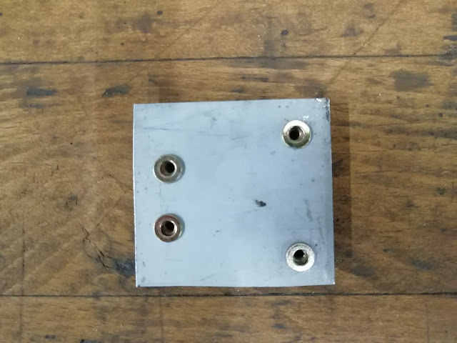
T
he small plate in detail, maybe total overkill to use 4 captive nuts, but where else can you ever use M3 captive nuts?!
Almost finished, card board template vs. finished article
and finally, everything installed with a small rubber seal on the bottom to avoid rattle and air flow:


